NPOL Reference File
Introduction
HST images can exhibit significant distortion, one of the severe cases being
ACS/WFC where it can reach 50 pixels. Anderson [Anderson2002] describes the total distortion
solution for ACS/WFC as consisting of a polynomial part which provides position
accuracy of 0.1-0.2 pixels, a filter dependent fine scale solution which brings the
accuracy of the positions to 0.01 pixels and a detector defect correction with a
maximum amplitude of 0.008 pixels. These distortion solutions are implemented
in the ACS pipeline as reference files. The IDCTAB files contain the polynomial distortion
and the DGEO files originally contained the combined solution for the detector
defect and the filter dependent fine scale residuals.
This document describes how the DGEO files are converted
to the new format, called NPOL files, and how they will be distributed and used. It also
describes the testing procedure of the NPOL files and provides an example of converting
and testing an ACS/WFC F606W DGEO file.
New representation - look-up tables
The fine scale distortions represented in the DGEO images can be stored in smaller look-up
tables without significant loss of information. These look-up tables follow the conventions
in the WCS FITS Distortion Paper [Calabretta2004]. Record-valued keywords are used to map an image in the science extension
to a distortion array in the WCSDVAR extension. This new type of FITS keywords has been
implemented in PyFITS and is fully described in [Calabretta2004]. Specifically, DPj.EXTVER in the science
extension header maps the science image to the correct WCSDVAR extension. The dimensionality
of the distortion array is defined by DPj.NAXES. Keywords DPj.AXIS.j in the SCI extension
header are used for mapping image array axis to distortion array axis. In the keywords above j
is an integer and denotes the axis number. For example, if distortion array axis 1 corresponds
to image array axis 1 of a SCI extension, then DP.1.AXIS.1 = 1.
A full example of the keywords added to a SCI extension header is presented in the last section.
The look-up tables are saved as separate FITS image extensions in the science files with EXTNAME
set to WCSDVARR. EXTVER is used when more than one look-up table is present in a single science
file. Software which performs coordinate transformation will use bilinear interpolation to get
the value of the distortion at a certain location in the image array. To fully map the image
array to the distortion array the standard WCS keywords CRPIXj, CRVALj and CDELTj are used. The
mapping follows the transformation
where  is the
 CRPIXj value in the distortion array which
corresponds to the  value in the image array, recorded as
CRVALj in the WCSDVARR header. Elements in the distortion array are spaced
by  pixels in the image array, where is the
 CDELTj
value in the distortion array header. In general can have
a non-integer value but cannot be zero. However, if the distortion array
was obtained as a subimage of a larger array having a non-integer step size
can produce undesirable results during interpolation. An example header for
ACS/WFC F606W WCSDVARR extension header is given in the last section.
A note about look-up tables
It is essential that the look-up tables meet two restrictions:
Every point in the corrected image is mapped to by not more than one point in the uncorrected image.
Every point in the corrected image is mapped to by at least one point on the corrected image.
This one-to-one (non-extrapolation) requirement can have implications on the geometry of the distortion array. If the distortion array is obtained as a subimage or subsample of a larger array, it is important that the edges of the distortion array coincide with the edges of the image.
Creating an NPOL file from a DGEO file
The DGEO files are FITS files with four image extensions with full chip size 4096x2048
pixels representing the residuals of the distortion in X and Y for the two ACS/WFC
chips. As described by Anderson [Anderson2002], the original tables from which the full size
DGEO images were created were sampled every 64 pixels to a size of 65x33 pixels.
Because of the coordinate transformations and many steps involved in creating the DGEO
files it was not possible to start with the original tables. Our purpose was to sample the full
size DGEO files in such a way that after interpolating them again the newly expanded
images would match the original images as close as possible. This is why we chose a
step size of 64 pixels for the sampling. Given the non-extrapolation restriction and
the requirement to have an integer step size we needed to sample an image of a size
4097x2049. We copied the last row/column of the DGEO images to the extra row/column
before sampling. This padding ensures that after bilinear interpolation there
all edge effects due to extrapolation will be minimized.
A Python script, makesmall.py, samples the large DGEO files and writes out the
small NPOL files. This code has been included in the REFTOOLS package in the
stsci_python distribution. The script also writes the sampling step size
in each direction to the headers of the NPOL file extensions. The step size is later
stored in the header of each WCSDVAR extension as the value of CDELT keywords to be
used by the software which does the coordinate transformation and interpolation.
Since the original DGEO files include the combined fine scale distortion and the
detector defect, it is imperative that the detector defect is removed from the DGEO
files before they are sampled. (The detector defect correction is stored also as a
D2IMARR extension and applied separately.)
Using NPOL files
STWCS.UPDATEWCS is used to incorporate all available distortion information for a
given observation in the science file. The name of the NPOL file which stores the
residual distortion for a specific science observation is written in the NPOLFILE
keyword in the primary header. UPDATEWCS copies the NPOL file extensions as WCSDVARR
extensions in the science file. The header of each WCSDVARR extension is also created
at this time following the rules in section 2 and the necessary record-valued keywords
are inserted in the science extension header so that the axes in the science image are
mapped to the correct WCSDVARR extension.
STWCS.WCSUTIL and its main class HSTWCS, as well as its base class PyWCS.WCS, can
read and interpret FITS files with WCSDVARR extensions. The method which performs
the bilinear interpolation and corrects the coordinates is p4_pix2foc(). All coordinate
transformation methods distinguish between 0-based and 1-based input coordinates
through the origin parameter.
A note about the fine scale distortion:
The original fine scale distortion was meant to be applied after the polynomial
IDCTAB distortion. In the new coordinate transformation pipeline the polynomial
distortion follows the SIP convention and the first order coefficients are
incorporated in the CD matrix which is used last in the pipeline to transform
from distortion corrected coordinates to sky coordinates. As a consequence residual
distortion arrays must be corrected with the inverse of the CD matrix since they will
be applied before the first order coefficients. UPDATEWCS performs this correction
for each extension of the NPOL file. However, when we test the NPOL files this
correction is omitted because the test does not require performing the entire coordinate
transformation pipeline from detector to sky coordinates.
Testing NPOL files
A Python script, REFTOOLS.test_small_dgeo.py, was written and made available for testing
of the NPOL files. The following procedure is implemented in the test script:
A science observation is run through
STWCS.UPDATEWCSto update the headers and create theWCSDVARextensions.An
HSTWCSobject is created from aSCIextensionA regular grid with the size of the image is created and is passed as input to
the
HSTWCS.det2im()method to account for the column correction reported in theD2IMreference file, thento the
HSTWCS.p4_pix2foc()method which applies bilinear interpolation to the WCSDVARR extension to the input grid.
The expanded NPOL file is compared to the original full size
DGEOfile and the difference images are (optionally) written to a file.
This comparison allows us to verify that the NPOL files get interpolated
to produce the exact same correction as provided by the DGEO files for the
same pixel position. Any further comparisons based on the full coordinate
transformation with and without these corrections get masked by the differences
in how the input FLT image coordinates get transformed to pixel positions
in the output image.
Results
The best way to verify that the transformation from sub-sampled NPOLFILE into
the full-frame represented by the full-size DGEOFILE was to use an artificial
DGEOFILE. This artificial DGEOFILE consisted of a strictly bilinear plane in
the DX and DY arrays. This should be something that the bilinear interpolation
routines in STWCS/PyWCS can exactly match when expanding the NPOLFILE, which
was created by sub-sampling the full-size DGEOFILE. This also allows us to
verify that we know how to specify the header for the NPOLFILE extensions
as written out to the FLT images to insure that the proper expansion gets
performed by STWCS/PyWCS.
The residuals from this comparison came out to be within single-point floating point precision with the exception of the edge effects in the last few rows and columns of the expanded array as seen here:
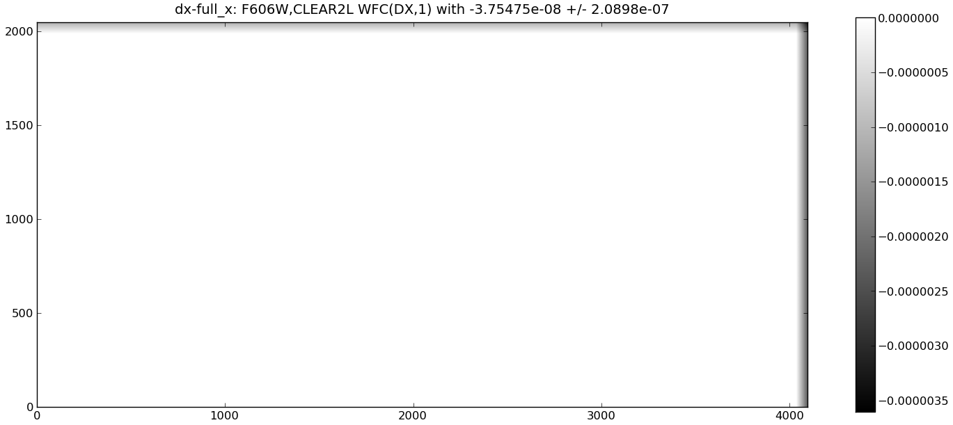
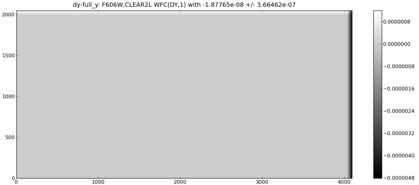
This test confirmed that the interpolation routine implemented within PYWCS will
correctly expand the NPOL file points to exactly recreate the DGEO file correction
for any given pixel position, except at the far ends of the columns of rows. The
variations at the ends of the rows and tops of the columns comes from edge effects
of the interpolation as it interpolates over 1 less pixel at the edges, however,
even these variations are well within numerical accuracy for the overall correction.
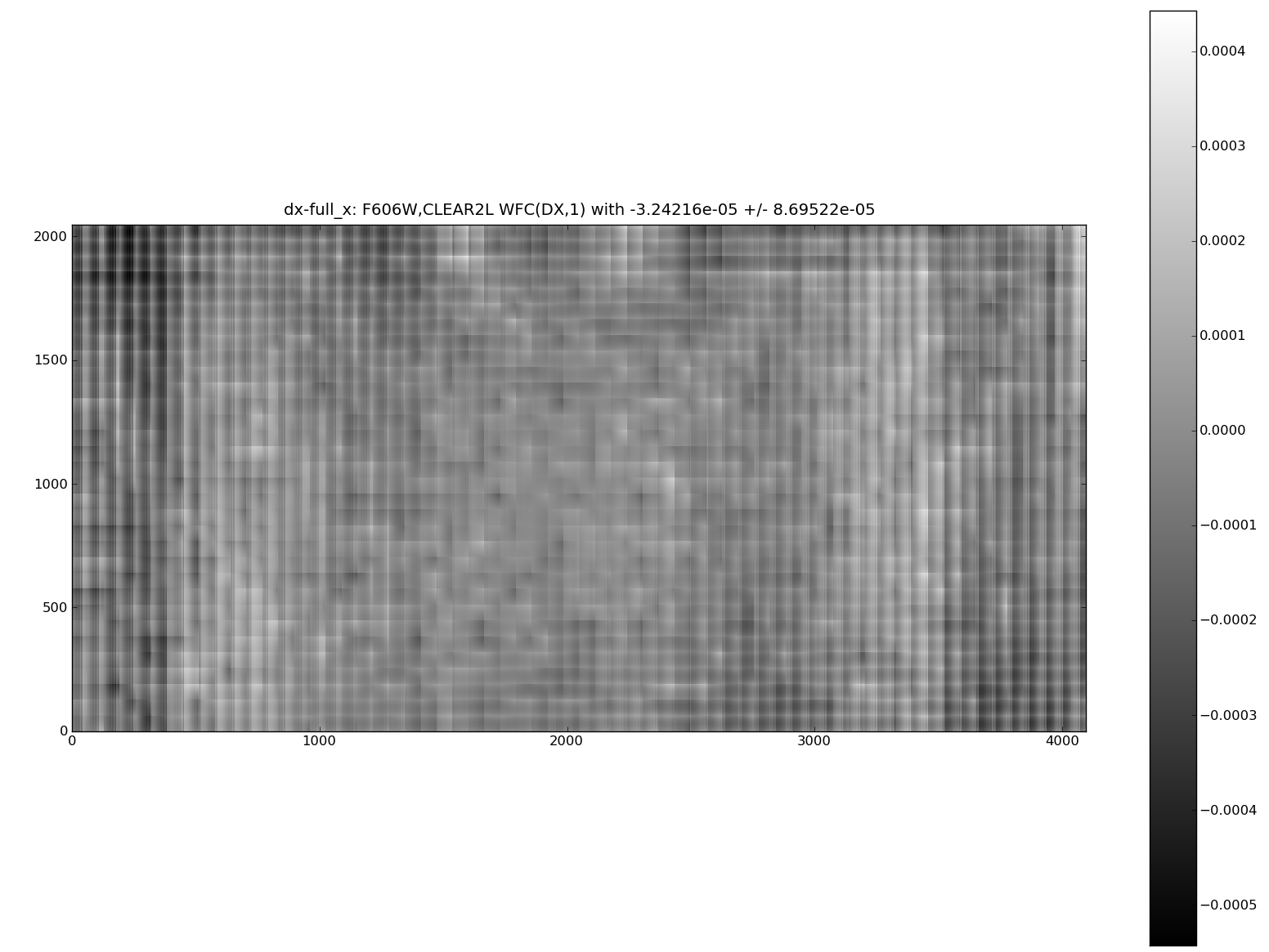
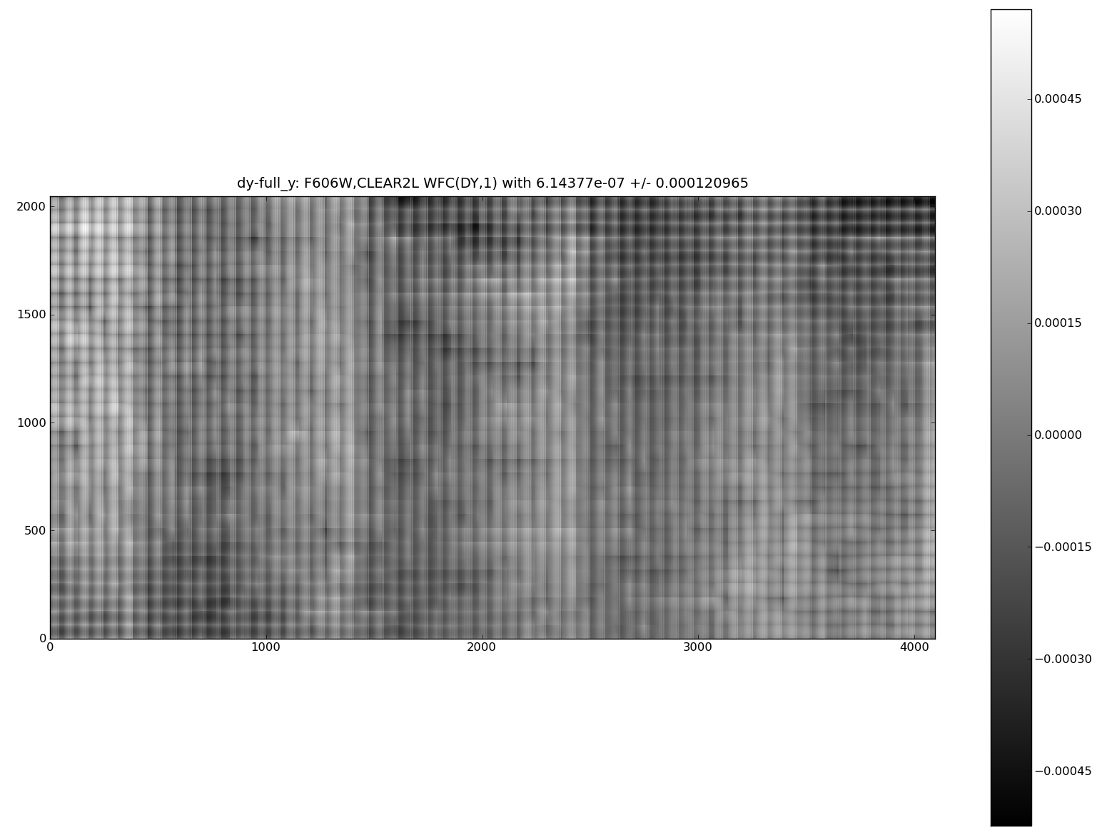
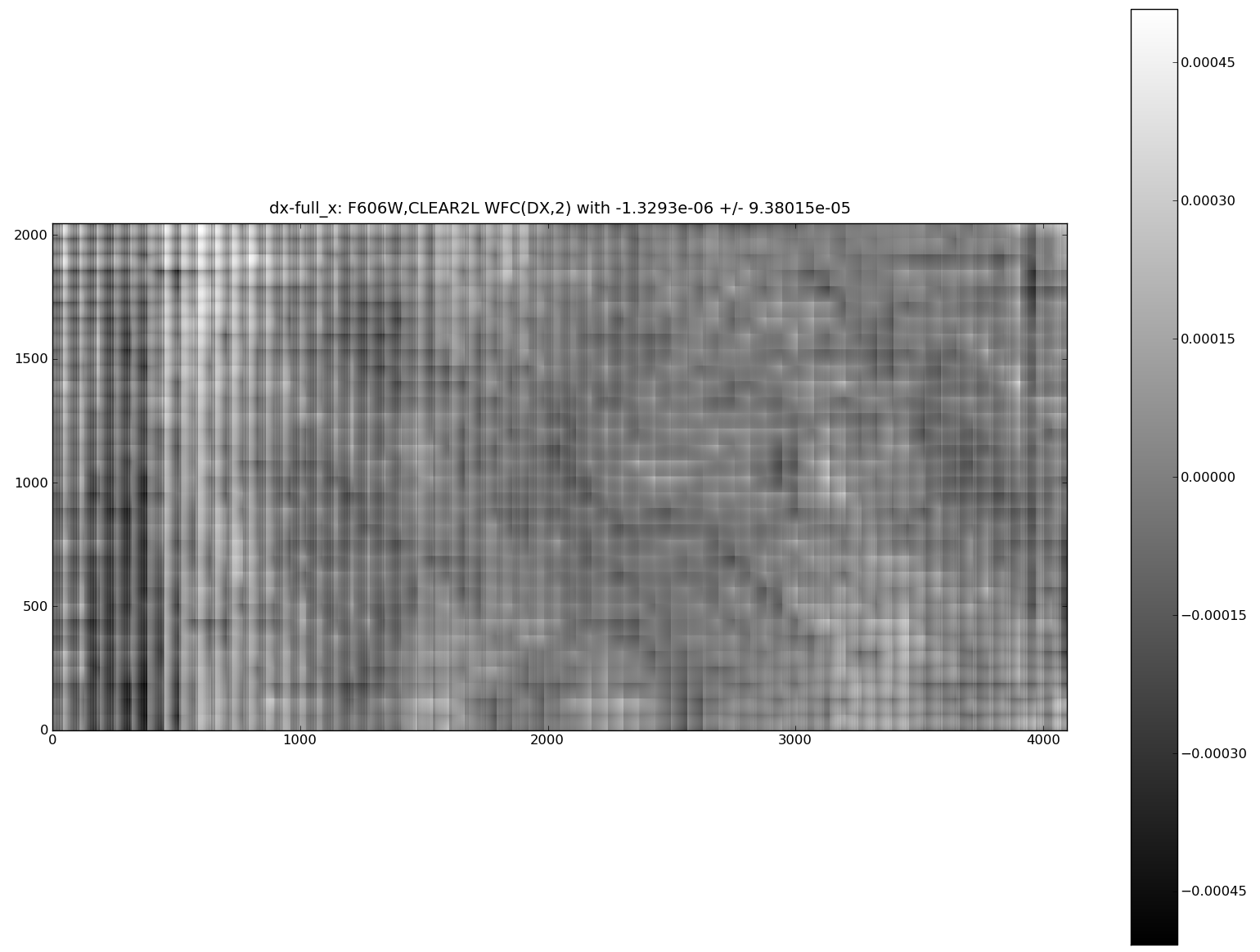
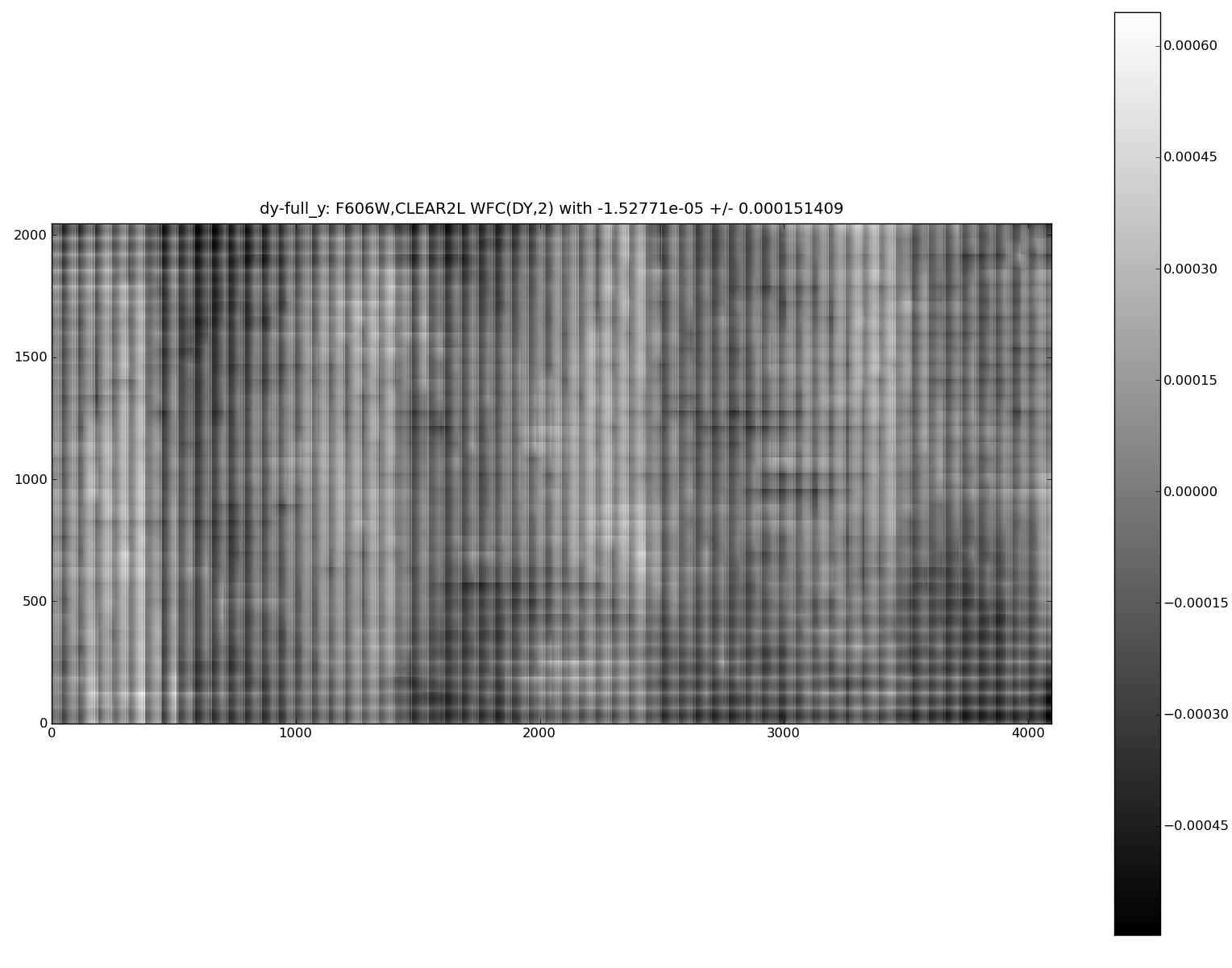
The new NPOL reference files were then compared to actual DGEO files
from CDBS for an ACS/WFC F606W image using this testing code. The test
image was run through STWCS.UPDATEWCS to populate the headers and write the
WCSDVAR extensions. Fig 3-6 show the difference between the DGEO files and
the expanded NPOL files for the two ACS/WFC chips in X and Y.
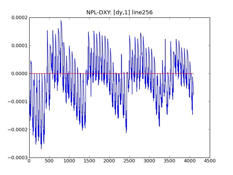
A random line from the difference image in X and Y is shown in the next two plots.
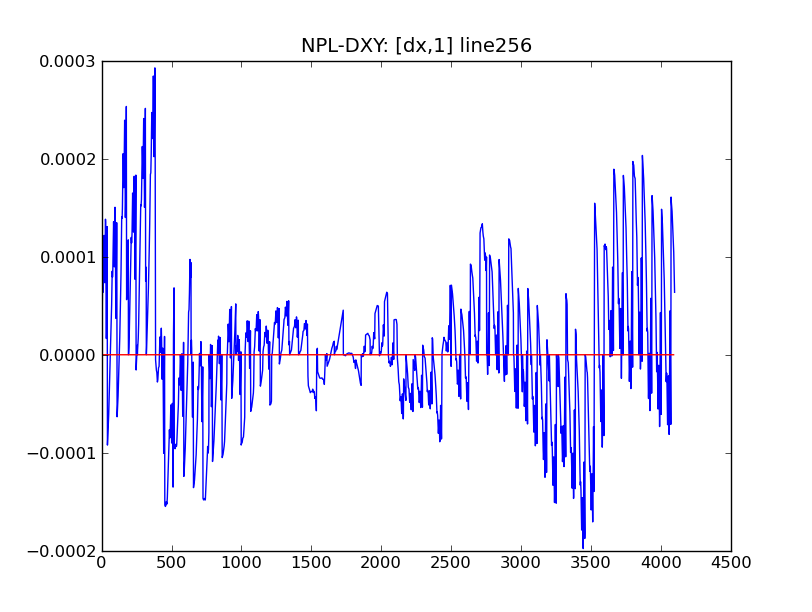
These results were used as the intial indication that the NPOL lookup tables accurately reproduce the same corrections as the original full-size DGEO reference images while avoiding the confusion of a full coordinate transformation. Further testing by the ACS Instrument Team will independently confirm whether or not the code and the new reference files accurately correct ACS images before these new reference files will be made available for general use or even for use in the pipeline.
Anderson, J. 2002, in the Proceedings of the 2002 HST Calibration Workshop, S. Arribas, A. Koekemoer, and B. Whitmore, eds
(draft FITS WCS Distortion paper) Calabretta M. R., Valdes F. G., Greisen E. W., and Allen S. L., 2004, “Representations of distortions in FITS world coordinate systems”,[cited 2012 Sept 18], Available from: http://www.atnf.csiro.au/people/mcalabre/WCS/dcs_20040422.pdf